SmartVueTM Process Control Panel for PID Controlled Pump Applications

What is SmartVueTM?

A key process controller for any pumping unit that requires precision pressure monitoring, PID control capabilities, and data acquisition with a graphical display in a small, rugged package.
  • Designed for the toughest industrial and municipal conditions
  • Armored, sunlight readable touchscreen display
  • Six Multipurpose I/O, configured as DI, DO, or VI
  • Operation In ANY climate: -40F to +158F (-40C to +70C)
  • 16 selectable J1939 parameter display screens
  • User-configurable inputs & process control, including PID
  • C1D2 Hazardous Area Classification (North America)
  • Data Logging

About SmartVueTM

Physical & Environmental Specs

Physical / Operational

  • Case color: Black
  • Dimensions: 3.6” (90 mm) High × 4.7” (119 mm) Wide × 4.8” (123 mm) Deep
  • Weight: 1.04 lbs (580 g)
  • Input Power Range 10 – 30 VDC, reverse polarity protected (external fuse recommended)
  • Power Consumption (no load): < 1 A
  • Power Consumption (max load): < 1.5 A

Panel Mount Info

  • Bolt Pattern: Identical to EMM620 Panel Meter – see Mounting Pattern Drawing for details.
  • Mounting Kit Accessories: Pan head Phillips screws (for various panel thicknesses) – 6/32 x 1/2″ (4), 6/32 x 5/8″ (4), 6/32 x 3/4″ (4)


Environmental

  • Operating Temperature Range:  -40F to +158F (-40°C to +70°C)
  • Storage Temperature Range: -40F to +176F (-40°C to +80°C)
  • Relative Humidity: 0 to 95%, non-condensing
  • Vibration: 4.4G, 3 axis, frequency swept 5-2000 Hz
  • Emissions Compliance: FCC part 15 Class A, Industry Canada
  • NEMA4 weatherproof panel-mount design
  • Class I Div. 2 (CSA/UL) Hazardous Location Compliance

Operational Specs

Protocols

  • Modbus ASCII, RTU, TCP (currently in testing)
  • J1939

Communication Interfaces

  • RS-232, RS-485
  • Ethernet

Current Loop Inputs

2 Dedicated 16-bit, 4-20 mA

  • Isolation: 500 Volts
  • High frequency analog filtering

Analog Outputs

2 14-bit linear (isolated) analog outputs

  • 4-20 mA up to 33 V max., or output for PID control

2 14-bit voltage outputs

  • 0 – 10 V with 100Ω output impedance
  • Maximum current of 10 mA

2 Frequency outputs

  • 0.00 Hz – 6250 Hz

Multipurpose I/O

6 Multipurpose I/O, configured as DI, DO,or VI

  • Digital Inputs:
    • 0-30 VDC
    • Configurable pull-up
    • Adjustable threshold voltage
  • Digital Outputs:
    • 0-30 VDC
    • Configurable pullup
    • Open collector
    • Output rating – 70mA max (hold), 140mA trip 1A peak, 50Ω impedance
  • Voltage Inputs:
    • 12bit with full scale 0 – 25 VDC
    • 100kΩ impedance

Hardware Counters

  • 2Tachometers, 80,000 Counts/second
  • 3Counters, 300,000 Counts/second
    • Configurable as 2 quadrature encoders

RTD Sensor Channel

116-bit (non-isolated) RTD

  • Pt 100 or 500 Ω DIN, IEC
  • Measurement range: -392 to +1562°F (-200 to +850 °C)

Modbus

  • Modbus Slave communications over RS-232/485
  • Supports Modbus RTU and Modbus ASCII protocols
  • Support for Function Codes 2 & 4
  • User configurable register mapping for all Process & Control Process data
  • Includes preassigned registers for J1939 SPN & DTC data

Data Logging

  • 450 MB data storage, > 14 million data points
  • Selectively log process, control, I/O, J1939 data
  • Configurable sampling period: 1 second to 24 hours
  • Auto file/log creation on power up or config. change
  • User configurable sequence names
  • Export data to USB (CSV format)
  • User configurable export – complete data sequence or time interval subset
  • Overwrite (looping) feature for continuous logging
  • J1939 diagnostic trouble codes stored separately

J1939

  • 16 selectable J1939 parameter display screens
  • Support DM1 active diagnostic codes
  • Support for PGN requests
  • Support VIN requests
  • ISOBUS support
  • Ability to disable transmit
  • Fixed and arbitrary addressable

User-Configurable

  • Inputs mapped to outputs
  • Control Loops: PID, signal conversion/ retransmission
  • Threshold triggers, latching or momentary
  • Direct output control from touchscreen


Frequently Asked Questions

If You Need More Help, Please Contact Our Team.

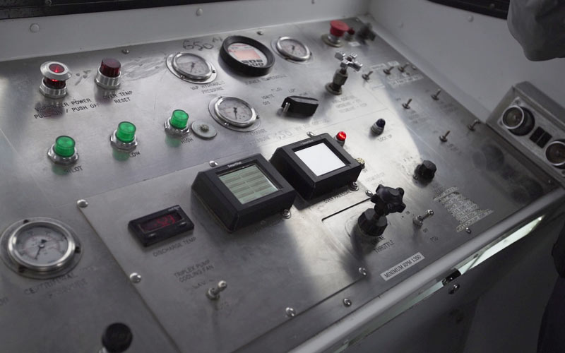
What are the Mounting Requirements?

Mounting requirements are reasonable, with the body of the SmartVue measuring 4.7″ x 3.6″ and a depth of only 3.5 inches. Of course – wiring will require additional space, but the mounting points on the Device should assist in minimizing depth requirements.  Details on the mounting can be viewed in the SmartVue Mounting Drawing.

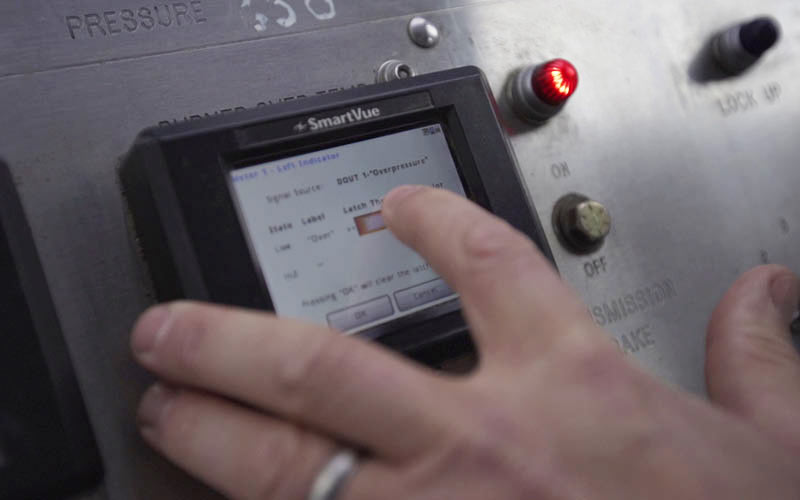
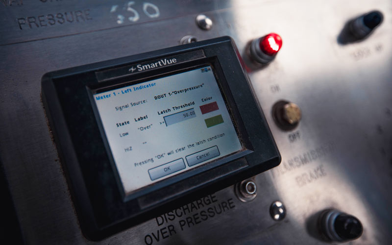
Can I modify the programming on the device for custom applications?

SmartVue supports a simple but practical programming interface, that will allow you to configure the device and tailor displays to meet your needs.  Contact the sales team if this is something you require for your project!

How Many Inputs and Outputs can be used concurrently?

Each SmartVue is configured with 6 multipurpose I/O ports – which can be configured as Digital inputs, Digital Outputs, or Voltage inputs.  This allows you to monitor 6 variables, or monitor and regulate 3. More information can be seen in the specifications.

How can I get data off the device?

SmartVue offers a number of methods for external monitoring and data analysis!

Live Data can be captured in a number of ways:

  • Serial MODBUS slave (read input registers)
  • Serial Data Stream (Comma Separated ASCII Data)
  • TCP/IP Data Stream (Comma Separated ASCII Data)
  • TCP/IP Remote Graphical Interface which allows you to view and interact with the live SmartVue display on a PC.

Logged Data is available through the means above, but also provides the facility to offload data to a USB memory device in CSV format.

Contact Dycor About SmartVue

Ready to Purchase? Questions About the Product?


    EvaluationLearn MoreOther

    * indicates required field.